
Welding & Metal Cutting Knowledge Hub
Explore technical guides, machine selection advice, and industrial fabrication insights backed by 60 years of engineering experience.
What Is a MIG Welding Machine and How Does It Work?
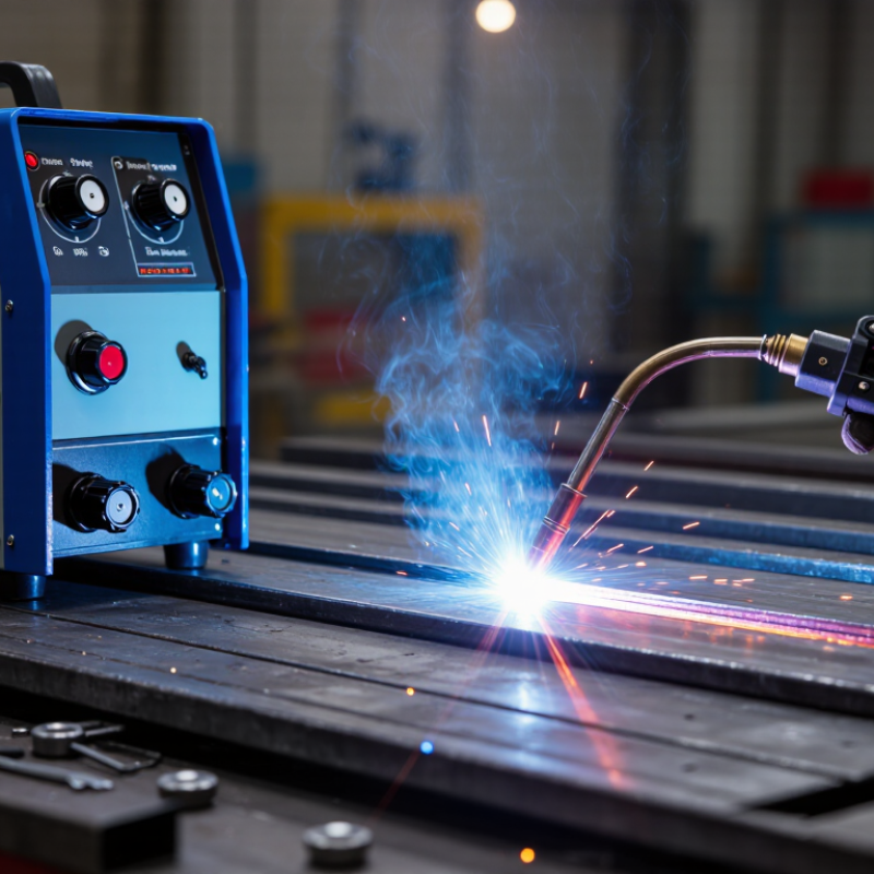
A MIG Welding Machine uses a continuously fed wire electrode, shielding gas, and an electric arc to join metal. The process is also called gas metal arc welding, or GMAW. When the trigger is pressed, the wire moves through the gun, melts, and forms a weld pool. Shielding gas protects that pool from oxygen and nitrogen. The result can look like a narrow, bright bead across steel, aluminum, or stainless steel.
The American Welding Society identifies GMAW as one of the most widely used arc-welding processes in manufacturing, repair, and fabrication. Grand View Research valued the global welding equipment market at approximately $16.9 billion in 2023, with continued growth expected through 2030. However, that figure covers several welding technologies, not only MIG equipment. This distinction matters. Market numbers can sound precise while hiding important differences.
Welding engineer John C. Lippold describes GMAW as “an arc welding process using a continuously fed wire electrode.” That definition explains the machine’s central advantage: steady wire delivery can improve production speed and reduce frequent electrode changes. In practical work, operators still need to control voltage, wire-feed speed, gas flow, torch angle, and travel speed. Small mistakes create spatter, porosity, or weak fusion.
It is not automatic perfection.
This guide will explain what a MIG Welding Machine contains, how the arc forms, and why settings change between materials and thicknesses. It will also examine machine types, shielding gases, safety practices, and common troubleshooting steps. Real workshop conditions are less predictable than product brochures suggest. Good results require knowledge, inspection, and repeated adjustment.
What Is a MIG Welding Machine?
A MIG welding machine is a power source that joins metal using a continuously fed wire electrode. MIG means metal inert gas, although many workshops use the term for related gas metal arc welding processes. The machine controls electrical current, wire speed, and arc voltage. A welding gun feeds the wire through a liner and contact tip. Shielding gas flows around the arc.
The process is direct and practical. The wire melts against the workpiece, forming a small pool of liquid metal. Gas protects this pool from oxygen and nitrogen in the air. Without adequate shielding, the weld may contain pores or develop a rough, unstable appearance. Common shielding gases include argon-based mixtures and carbon dioxide blends. The correct choice depends on the metal, thickness, and required bead profile.
MIG equipment is useful for steel, stainless steel, and aluminum fabrication. It can produce clean welds quickly, but it is not effortless. A technician must adjust settings for joint design, wire diameter, and material thickness. Too much wire speed can create a harsh, stubbing arc. Too little can produce excessive spatter. Keep the gun near the correct angle and distance. Small changes matter. In practice, a smooth bead does not always prove a strong joint. Surface cleaning, penetration, and inspection still require careful attention. I would not trust appearance alone.
Typical MIG Welding Current Ranges by Wire Diameter
A MIG welding machine feeds a continuous wire electrode through a welding gun while shielding gas protects the molten weld pool. Larger wire diameters generally support higher welding currents and are commonly used for thicker steel. The ranges shown are typical settings for mild steel and may vary with material thickness, joint design, shielding gas, and transfer mode.
How MIG Welding Machines Generate and Control the Welding Arc
A MIG welding machine creates an electric arc between a continuously fed wire electrode and the workpiece. The arc melts both materials, forming a small pool of liquid metal. A shielding gas flows through the torch nozzle and reduces contact with oxygen and nitrogen. Without adequate shielding, the weld may become porous, weak, or visibly rough.
The power source usually maintains a constant voltage while the wire feeder controls electrode speed. Faster wire feed increases current and adds more metal, but excessive speed can cause stubbing and spatter. Voltage changes the arc length and bead profile. Higher voltage often produces a flatter bead, while lower voltage can make the arc harsh and unstable. Internal feedback circuits monitor electrical changes within milliseconds. They adjust output to keep the arc usable as the torch moves.
Arc control still depends heavily on the operator. Torch angle, travel speed, contact-tip distance, and gas flow all affect heat transfer. In a workshop, I check the ground connection and listen to the arc before trusting the bead. A steady frying sound is useful, though it is not a perfect diagnosis. Wind, dirty steel, or an incorrect gas setting can disturb the arc quickly. I have also found that recommended settings sometimes need small adjustments for joint fit-up and material thickness. That judgment comes from testing, inspection, and careful review of the finished weld.
What Components Make Up a MIG Welding Machine?
A MIG welding machine combines several parts that must work together smoothly. The power source converts incoming electricity into a controlled welding current. Its control panel adjusts voltage and wire speed for different metals and thicknesses. A stable arc depends on both settings, not one control alone.
The wire spool holds the consumable electrode. A motor-driven wire feeder pushes this wire through a liner inside the welding gun. At the gun’s end, the contact tip transfers current to the wire. The nozzle directs shielding gas around the arc and molten pool. A regulator and hose control gas flow from the cylinder, while a ground clamp completes the electrical circuit.
The details matter.
During welding, the wire melts into the joint while the gas limits contact with oxygen. Clean metal, correct polarity, and steady travel speed usually produce a stronger bead. In practical workshop use, a partially blocked nozzle can disturb gas coverage and create porosity. That fault is easy to overlook.
I have also found that recommended settings are starting points, not guarantees. Wind, rusty surfaces, wire diameter, and joint position can change the result. The machine may sound normal while the weld remains weak. Inspect the bead, listen to the arc, and check the finished joint against suitable welding requirements. Wear proper eye, hand, and body protection, and confirm ventilation before operating the equipment.
How the MIG Welding Process Works Step by Step
A MIG welding machine feeds a continuous solid wire through a gun while shielding gas protects the molten metal. The process is formally classified as process 131 under ISO 4063. It begins when the operator selects wire diameter, voltage, wire-feed speed, and gas flow. The settings must match the metal thickness and joint design. Small errors matter.
When the trigger is pressed, the wire advances and an electric arc forms between its tip and the workpiece. The arc melts both the wire and a narrow area of the base metal. A bright weld pool appears. The operator moves the gun steadily, usually keeping a short stick-out and a consistent travel angle. Shielding gas should cover the pool continuously. Drafts can disturb it.
As the gun travels, the pool cools into a visible bead. The operator then checks its width, penetration, spatter, and surface shape. In real workshops, the first pass is rarely perfect. Too much wire speed can create a crowded, unstable arc. Excessive voltage may widen the bead and increase spatter. According to the U.S. Bureau of Labor Statistics’ 2024 Occupational Outlook data, welding occupations may have about 42,600 openings annually from 2023 to 2033, making process control a practical workplace skill. Guidance from the American Welding Society also emphasizes procedure qualification, inspection, and operator training. Clean preparation still matters. Fancy settings cannot repair contaminated steel.
Which Materials and Applications Suit MIG Welding?
MIG welding suits many workshop and fabrication tasks because it feeds a continuous wire electrode through a welding gun. The arc melts the wire and base metal, while shielding gas protects the molten pool from air. Mild carbon steel is the most forgiving choice. It works well for brackets, frames, vehicle repairs, gates, and general structural fabrication. Stainless steel can also be welded, but it needs suitable wire, gas, and careful heat control. Aluminum is possible with the right wire-feeding setup, although its soft wire demands a clean liner and steady technique.
Material thickness matters. Short-circuit transfer handles thinner sheet metal and reduces heat input. Larger sections may need spray or pulsed transfer for deeper, smoother penetration. Clean edges are essential. Paint, oil, rust, and mill scale can create porosity or weak fusion. A bright bead is not proof of strength.
MIG welding is less reliable outdoors because wind can disturb the shielding gas. Galvanized steel requires controlled preparation and strong ventilation because its coating can produce hazardous fumes. Cast iron is usually a poor match for routine MIG work. Thin panels may burn through before the operator notices. I have seen attractive welds fail after vibration exposed hidden contamination. A small test joint, correct settings, and proper protective equipment remain more dependable than guessing.
FAQS
It feeds a continuous wire toward the workpiece. An electric arc forms between the wire tip and metal. The arc melts both materials into a small weld pool.
Shielding gas protects molten metal from oxygen and nitrogen. Poor coverage can cause pores, weak fusion, and rough surfaces. Wind can disrupt protection quickly.
Faster wire speed usually increases current and deposited metal. Too much speed may cause stubbing and spatter. Higher voltage often creates a flatter, wider bead.
Choose wire diameter, voltage, wire-feed speed, and gas flow. Match them to material thickness and joint design. Small setting errors matter.
Mild carbon steel is usually the easiest material. Stainless steel and aluminum can also work with suitable equipment. Aluminum needs clean wire-feeding parts and steady technique.
Remove paint, oil, rust, and mill scale before welding. Contamination can cause porosity or weak fusion. A shiny bead proves little.
Check bead width, penetration, spatter, and surface shape. Listen for a steady frying sound, but do not trust sound alone. A small test joint can reveal problems.
Outdoor wind can scatter shielding gas. Thin panels may burn through before the operator reacts. Dirty steel and poor grounding also disturb the arc.
Not always. Joint fit-up and thickness may require small adjustments. I still need testing and inspection before trusting a bead. Good judgment develops slowly.
Conclusion
A MIG Welding Machine is a versatile welding system that joins metal by feeding a continuously supplied wire electrode through a welding gun while shielding the weld area with gas. It generates an electric arc between the wire and the workpiece, creating enough heat to melt both the electrode and the base metal. Adjustable voltage, wire-feed speed, and gas flow help control arc stability, penetration, bead shape, and overall weld quality.
The main components typically include a power source, wire spool, drive rollers, welding gun, contact tip, shielding-gas system, cables, and a work clamp. During operation, the user prepares and positions the materials, selects suitable settings, starts the arc, and moves the gun steadily along the joint while the wire and gas are supplied automatically. MIG welding is well suited to materials such as mild steel, stainless steel, and aluminum, making it useful for fabrication, repairs, automotive work, construction, and general metal projects.

Blog Tags: